Grove Red LED
Last updated
Was this helpful?
Last updated
Was this helpful?
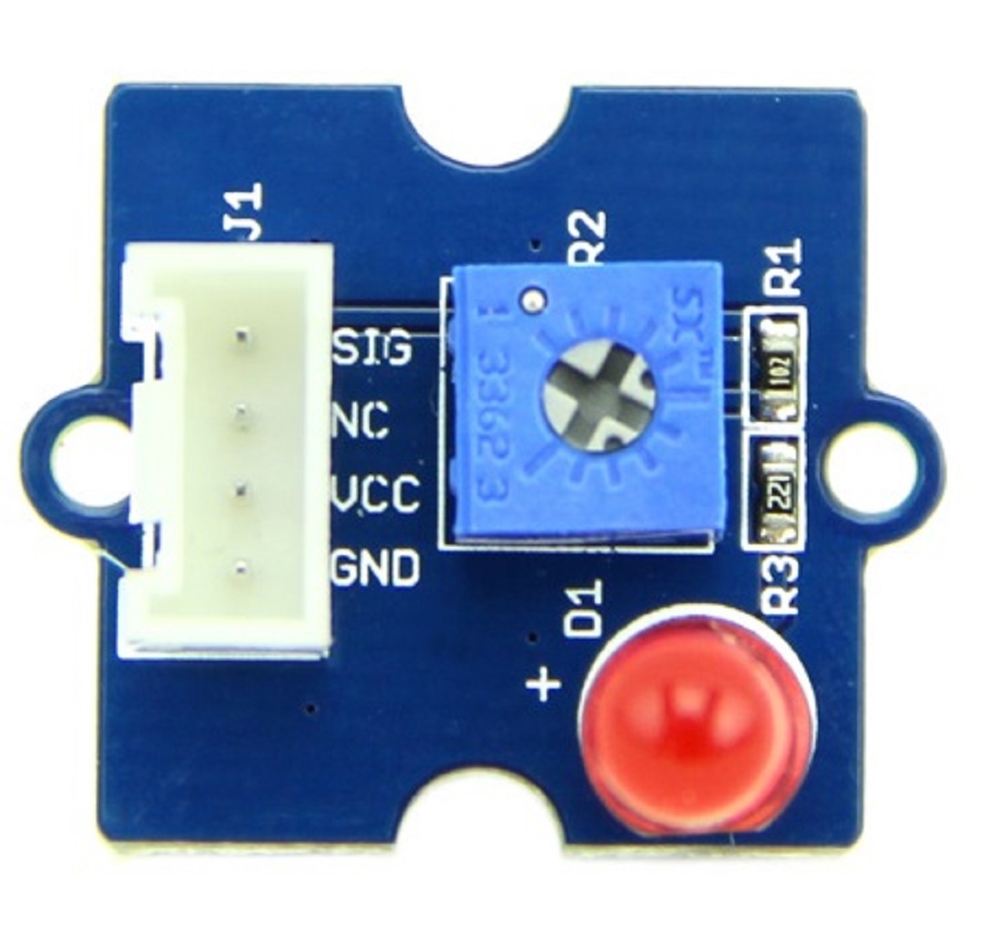
Grove - Red LED is similar to the module in that it houses an LED light source. In addition, it also has a potentiometer on-board to manage the power requirements of the LED. The PCB of this module has mounting holes using which it can be mounted on the required surface for your prototype. For example, it can be easily used as a pilot lamp for indicating power or signal presence.
Provides an LED light source for your project
Flexibility to replace Red LED with any other LED, e.g., that of a different color since the LED is 'pinned in' into the LED holder rather than soldered on to the board
On-board potentiometer guarantees brightness control and interoperability with a higher range of input voltages
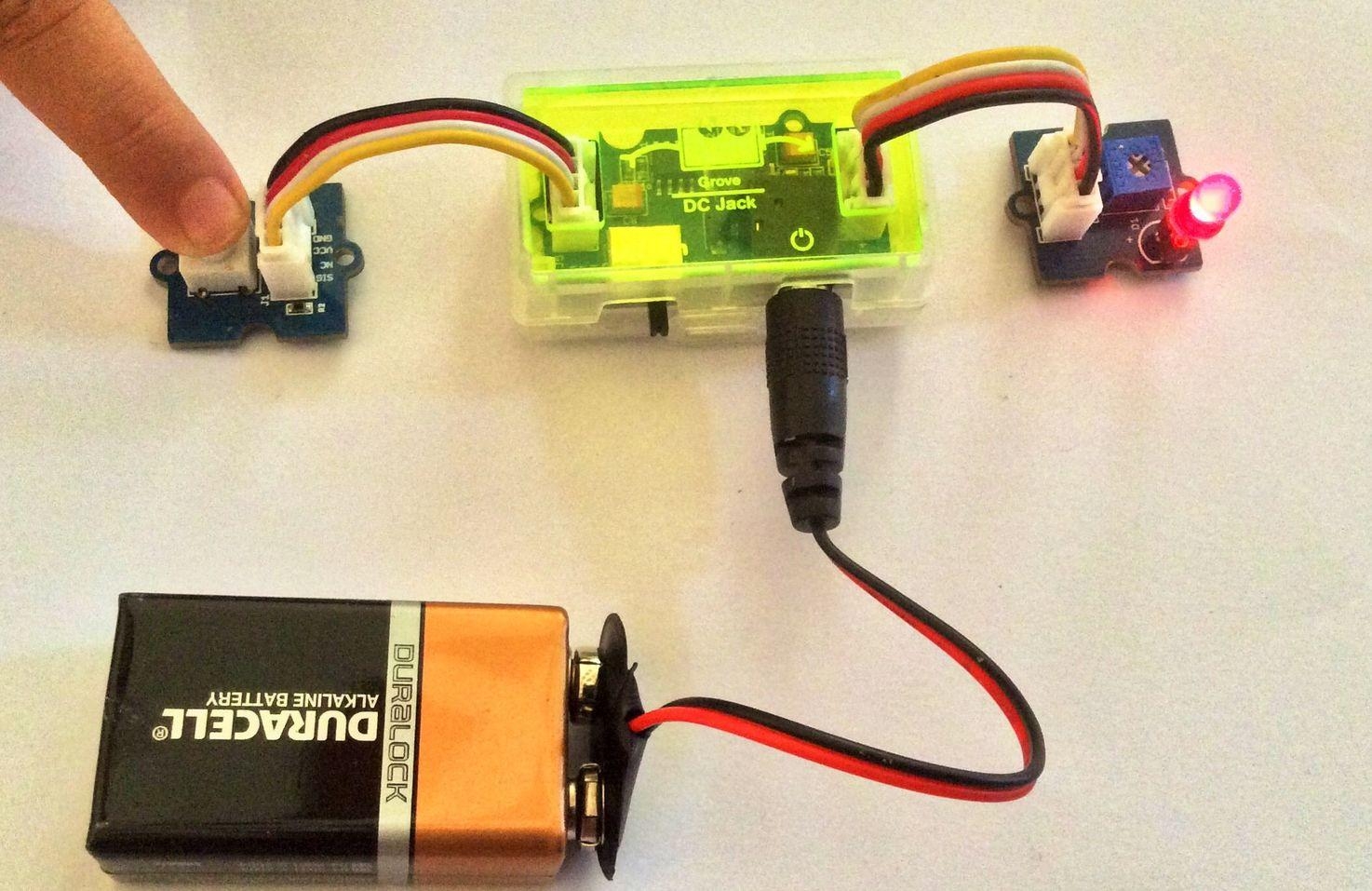
Follow these steps to build a sample circuit using this module:
2.Power up the circuit.
3.The LED will turn ON when the input module supplies a trigger:
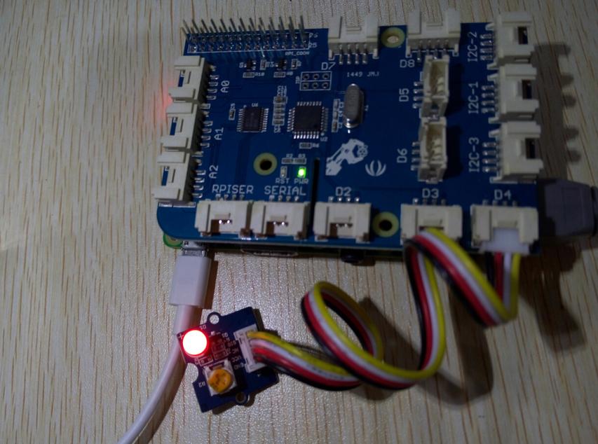
Connect the LED to Port D4 and power on the Raspberry Pi, using the Grove wire connector.This is a test to make led blinking.You can connect to GrovePi+ with it as the picture below.
Find the path to the file(According to your own path)
Run Program
1.Connect the LED module to the output side of your circuit (to the right of the power module). On the input side of the circuit, you may use a range of sensor based input modules (, , or ).
If using with a momentary switch like the one on the module, simply press the button to turn ON the LED:
If using with a , move the slider from the GND position to VCC and see how the brightness of the LED increases as the supplied voltage increases.
If using with a connected directly to the input side of the circuit, you should see the LED turn ON in bright light and turn OFF in the dark. If you want the LED to turn ON only in the dark, add a module between the light sensor and the power module.
You can use either the module or the module for the Grove circuit when using in standalone mode (without MCU). When used in conjunction with an MCU board such as an or and a , the power is supplied to the circuit through the microcontroller board and there is no need to use any .
This module is available as part of the following :
The uses the module.
Alternatively, it can be bought stand-alone at the .
Also see section for Eagle files for this module