Grove Serial RF Pro

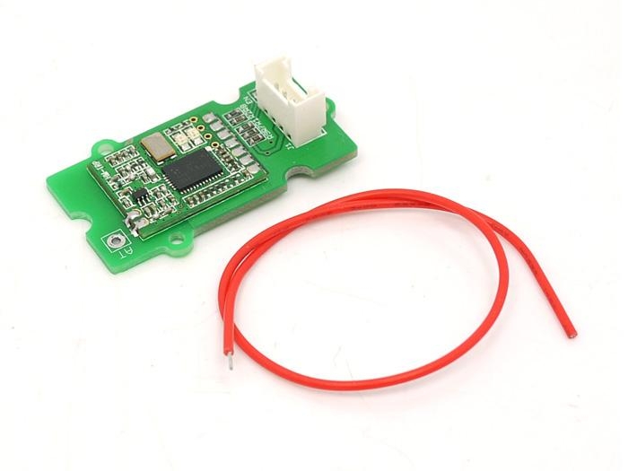
Grove-Serial RF Pro is a low cost, high performance transparent FSK transceiver with operating at 433/470/868/915 MHz, and the best performance is at 433M(Default). There is a UART interface that is easy to realize the wireless data transmission with only providing the UART data. It is flexible for the users to set the UART baud rate, frequency, output power, data rate, frequency deviation, receiving bandwidth etc parameters. It is your ideal choice for designing wireless data transmission products which can be widely used on wireless data transmission field.
Version Tracker
Revision
Descriptions
Release
v0.9b
Initial public release
NA
Features
Grove compatible
High output power
High output power
Small size
Longer transmission distance
Application Ideas
Remote control, remote measurement system
Wireless meter
Access control
Identification system
Data collection
IT household appliance
Baby monitoring system
Specification
Item
Min
Typical
Max
Unit
Working Voltage
4.75
5.0
5.25
VDC
Current at sleep mode
1
uA
output power
1
-
20
dB
Communication Speed
1.2
-
115.2
Kbps
Transmission Distance(Max)
1
Km
Sensitivity
-117
dBm
Communication Protocol
UART
/
Operate Temperature
-40
-
+85
℃
Interface Function

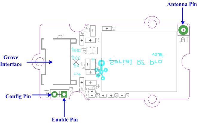
Pad Type (5V Logic level)
Description
G(GND)
Ground port
EN(ENABLE)
Set low for normal mode as data transceiver (Default is low with 10k to GND). Set high to put into sleep mode.
CON(CONFIG)
Set low for configuration mode (connect to GND). Set high for communication (Default is high).
RX
UART Data input
TX
UART Data output
V(VCC)
Designed for 5V(+)supply
AT
Antenna pin
Getting Started
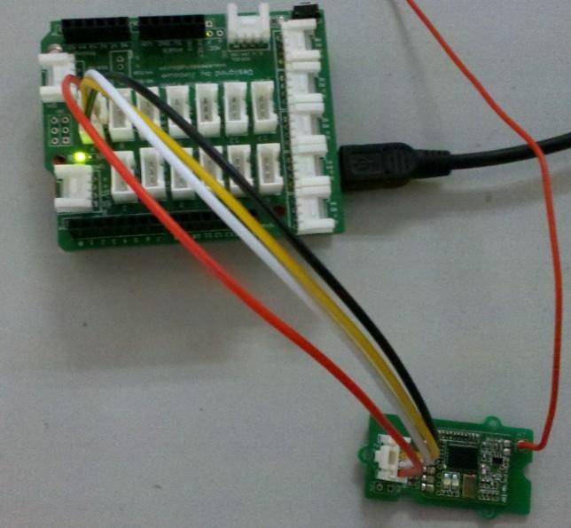
Here we show two RF Pro Grove units mutually transmitting/receiving data. You need two RF Pro Grove units and two Seeeduino to do the demo.
Connect one Grove - Serial RF Pro to UART of Grove - Base Shield and plug Grove - Base Shield into Seeeduino.

Connect another Grove - Serial RF Pro to Seeeduino using the same method.
Config and Inquiry methods
The module will be ready for Config status if ENABLE pin is low, CONFIG pin is low. It will be in Config if the red and green LED keep lighting. Then you can Config & inquiry on the module.
Connect CON pin to LOW/GND to enter configure mode.
Send command to modify and query the config of the module. Config & Inquiry instruction description see Reference.
The Config instruction format is as AA+FA+[instruction]+[parameter]. The instruction is 1 byte, the parameter is the HEX data of 0-4 bytes (in big-endian ordering, with the high byte before the low byte).
Note:
1) Do remember the UART transfer speed (default is 9600, better not change) if you make some change, or you won't be able to control the module. The instruction’s transfer speed will change accordingly if changes the transfer speed of UART. The range of transfer speed of the instruction is from 1.2Kbps – 115.2K bps.
2) LED Function Description:
The red and green LED will flash when there is power and the module is working.
The module will be ready for configuration mode if EN(ENABLE) pin is low(default is low),CON(Config) pin is low. When in configuration mode, the red and green LED will both be solidly lit. - The green and red LED will not be solidly lit if the module is not in configuration mode.
The red LED flash when the module is transmitting, the red LED will be off when the transmission is finished.
The green LED is off when the module is waiting for data to be received, the green LED will flash once when the module receives data.
</dd></dl>
</dd></dl>
Communication Mode
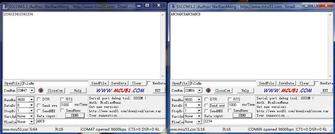
Upload the below code into Seeeduino, Please click here if you do not know how to upload.
You can see as show below after open serial monitor.

Reference
The following table lists the commands and responses involved in interacting with Serial RF Pro v0.9b.
Instruction(HEX)
Description
Config instruction(HEX)
Return Value
F0
Reset to default parameters (except UART transfer speed), no parameter follows
AA FA F0
4F 4B 0D 0A (OK /r/n)
E1
Reading the current Config parameter, no parameter follows
AA FA E1
16 bytes: (**following the order below**)
D2
Set up working frequency,[parameter]4 byte,[parameter] Unit :Hz. Set up range: * HM-TRP-433: 414000000-454000000Hz; * HM-TRP-470: 450000000-490000000Hz; * HM-TRP-868: 849000000-889000000Hz; * HM-TRP-915: 895000000-935000000Hz
Example: * Config instruction: AA FA D2 **36 89 CA C0**, set up frequency as 915000000Hz.(**0x36 89 CA C0=915000000**) * Config instruction: AA FA D2 **19 DE 50 80**, set up frequency as 434000000Hz.(**0x19 DE 50 80=434000000**)
4F 4B 0D 0A (OK /r/n)
C3
Set up wireless data rate,[parameter]4 byte,[parameter] unit :bps. Set up range:1200-115200 bps
Example: * Config instruction: AA FA C3 **00 00 25 80**,set up transfer speed as 9600bps.(**0x00 00 25 80=9600**) * Config instruction: AA FA C3 **00 00 96 00**, set up transfer speed as 38400bps.(**0x00 00 96 00=38400**)
4F 4B 0D 0A (OK /r/n)
B4
Set up receiving bandwidth,[parameter]2 byte,[parameter]Unit :KHz Set up range:30-620KHz
Example: * Config instruction: AA FA B4 **00 69**, set up receiving band as 105KHz.(**0x00 69=105**) * Config instruction: AA FA B4 **01 2C**, set up receiving band as 300KHz.(**0x01 2C=300**)
4F 4B 0D 0A (OK /r/n)
A5
Set up frequency deviation,[parameter]1 byte,[parameter]Unit :KHz Set up range:10-160KHz
Example: * Config instruction: AA FA A5 **23**, set up modulation frequency as 35KHz.(**0x23=35**) * Config instruction: AA FA A5 **32**, set up modulation frequency as 50KHz.(**0x32=50**)
4F 4B 0D 0A (OK /r/n)
96
Set up transmission power ,[parameter]1 byte,0~7level Set up range:0-7level(1-20 dBm)
Example: * Config instruction: AA FA 96 **07**, set up transmission power as level 7 (+20 dBm) * Config instruction:AA FA 96 **03**, set up transmission power as level 3 (+8 dBm)
4F 4B 0D 0A (OK /r/n)
1E
Set up UART transfer speed,[parameter]4 byte,[parameter] unit: bps Set up range:1200-115200 bps
Example: * Config Instruction :AA FA 1E **00 00 25 80**,set up speed as 9600bps.(**0x00 00 25 80=9600**) * Config instruction :AA FA 1E **00 00 96 00**, set up speed as 38400bps.(**0x00 00 96 00=38400**)
4F 4B 0D 0A (OK /r/n)
87
Wireless signal strength when receiving useful data, follows no [parameter]
Config Instruction:AA FA 87 
RSSI value is 8 bit, range: 0-255
78
Disturb wireless signal strength, follows no [parameter] Note: * Modulation index : h = Fd/Rb, Range is 0.5 ~ 32. * If h>1, BW =Rb+2Fd; If h<1, BW =2Rb+ Fd.
Config Instruction:AA FA 78
RSSI value is 8 bit , range: 0-255
Resources
[Code] Serial RF Pro Demo Code
Last updated