
Grove BLE dual model v1.0
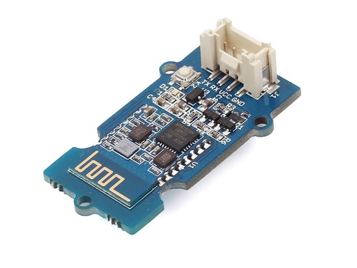
Grove - BLE (dual model) v1.0 uses CSR dual mode Bluetooth chip. The chip is based on ARM architecture and supports AT instructions. Users can develop flexibly according to the serial baud rate, equipment name, pairing password.
[![]() ](https://www.seeedstudio.com/Grove-BLE-(dual-model)-p-2407.html)
](https://www.seeedstudio.com/Grove-BLE-(dual-model)-p-2407.html)
Features
BT Version: Bluetooth Specification V4.0 & BLE
UART send and receive max bytes is 512
Other device to module in SPP mode: 90 Bytes per packet
Other device to module in BLE mode: 20 Bytes per packet
Two data transmission mode, balance mode and high speed mode
Working frequency: 2.4GHz ISM band
Modulation method: GFSK(Gaussian Frequency Shift Keying)
RF Power: -23dbm, -6dbm, 0dbm, 6dbm.
Speed: Asynchronous: 3K Bytes
Synchronous: 3K Bytes
Security: Authentication and encryption
Service: Slave SPP, Peripheral BLE, UUID FFE0,FFE1
Power: +3.3/+5.0VDC 50mA
Long range: SPP 30 meters, BLE 60 meters
Power: SPP 13.5mA, BLE 9.5mA
Working temperature: –5 ~ +65 Centigrade
!!!Tip More details about Grove modules please refer to Grove System
Platforms Supported
Hardware Overview
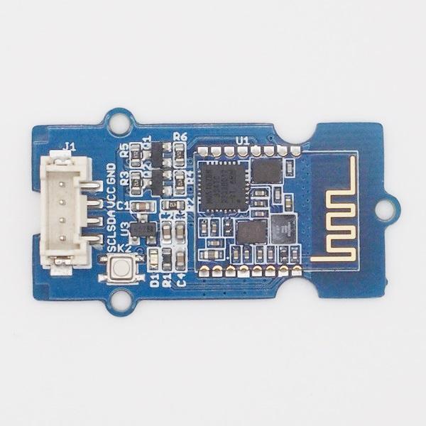
K2: During connected status, it could be disconnected by pressing K2 button more than 100ms. During sleep mode, it could be restored through pressing K2 (factory settings) button.
U1: U1 is the wireless module, it includes automatic power on reset circuit.
D1: The LED works in two mode: Sleeping is indicated by flashing slowly and Connected status indicated by continuous illumination.
J1: The standard Grove connector.
Caution BLE transmission speed is slower than SPP transmission, so we selected the lower one in the design, in accordance with the speed of a BLE dual-mode product planning.
Hardware Installation
Connecting Bluetooth to PC through UART Bee
The Bluetooth provides a serial port with standard Grove socket, most USB-UART converter can be used. Here we use a UartSBee V5 to connect Bluetooth and PC. 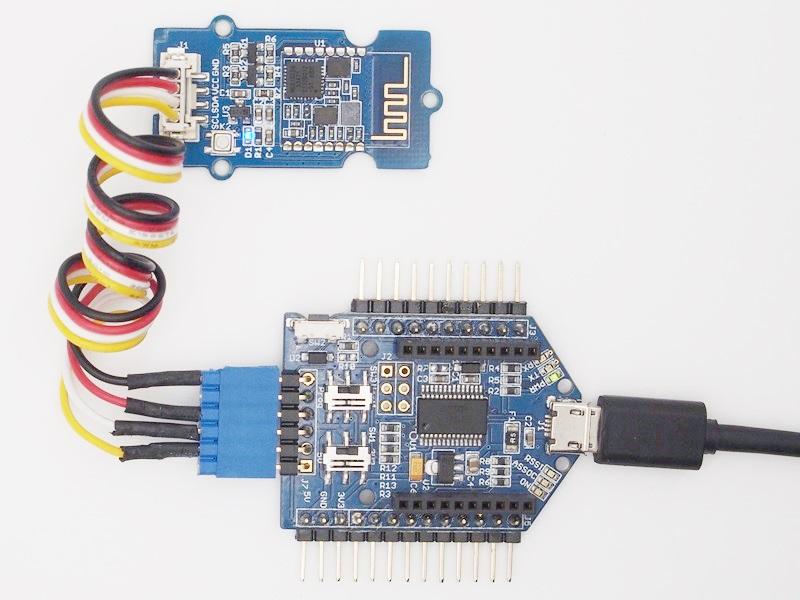
Connecting Bluetooth to Arduino
Since Arduino Uno have no Grove socket, we use Seeeduino Lotus instead. You could use Arduino with Grove Base Shield V2 as well. As an example, D2 and D3 are used as software UART. So, plug the Grove cable into "D2" socket 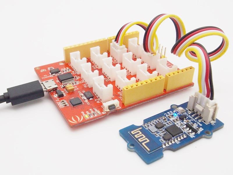
Software Instructions
Conventions
In EDR mode, only slave can be configured while either master or slave can be in BLE mode.
Factory default setting:
EDR Name HMSoft, Slave role, PinCode 1234
BLE Name HMSoft, Slave role, PinCode 000000
Baud: 115200, N, 8, 1;
AT Command format:
Uppercase AT command format. string format, without any other symbol. (e.g. \r or \n).
Any incorrect command would get no response.
AT Commands
1. Test Command
Send
Receive
Parameter
AT
OK/ER/Disconnect link
None
If module is not connected to remote device will receive: “OK”
If module has an error, will receive: “ER”
If Module has connected, module will disconnected from remote device, if “AT + NOTI” is setup to 1, will receive information string
2. Query module EDR address
Send
Receive
Parameter
AT+ADDE?
OK+ Get: MAC
None
3. Query module BLE address
Send
Receive
Parameter
AT+ADDB?
OK+ Get: MAC
None
4. Query/Set Authentication mode
Send
Receive
Parameter
Q: AT+AUTH?
OK+ Get:[P1]
P1: 0, 1, (Default: 0) 0 – Not authentication 1 – Must authentication
S: AT+AUTH[P1]
OK+ Set:[P1]
AT+AUTH0: allow made an insecure connection. AT+AUTH1: every connection must with authentication.
5. Query/Set A to B mode
Send
Receive
Parameter
Q: AT+ATOB?
OK+ Get:[P1]
P1: 0, 1, (Default: 0) 0 – Not Open ATOB 1 – Open ATOB mode
S: AT+ATOB[P1]
OK+ Set:[P1]
This command must work with AT+MODE0 command. When A device (SPP mode) connect to the module and B device (BLE mode) is also connect to the module, The data string from A device send to the module will send to B device. The data string from B device send to the module is also send to the A device.
6. Query/Set baud rate
Send
Receive
Parameter
Q: AT+BAUD?
OK+ Get:[P1]
P1: 1~7, (Default: 6). 1 - 4800 2 – 9600 3 – 19200 4 – 38400 5 – 57600 6 – 115200 7 - 230400
S: AT+BAUD[P1]
OK+ Set:[P1]
7. Clear bond information
Send
Receive
Parameter
AT+BONDE
OK+BONDE
Clear EDR bond info
AT+BONDB
OK+BONDB
Clear BLE bond info
BLE mode not supports it yet.
8. Clear Last Connected EDR Device Address
Send
Receive
Parameter
AT+CLEAE
OK+CLEAE
None
9. Clear Last Connected BLE Device Address
Send
Receive
Parameter
AT+CLEAB
OK+CLEAB
None
10. Query/Set Module DUAL Work Mode
Send
Receive
Parameter
Q: AT+DUAL?
OK+ Get:[P1]
P1: 0, 1, (Default: 0) 0 – Allow dual connect. 1 – Allow one connect.
S: AT+DUAL[P1]
OK+ Set:[P1]
AT+DUAL0: allow two connections at same time (SPP and BLE). AT+DUAL1: Only allow one connection at same time (SPP or BLE)
11. Query/Set hardware flow control switch
Send
Receive
Parameter
AT+FIOW?
OK+ Get:[P1]
P1: 0, 1,(Default: 0) 0: Hardware flow control off 1: Hardware flow control on
AT+FIOW[P1]
OK+ Set:[P1]
12. Query/Set module data transmission speed mode
Send
Receive
Parameter
AT+HIGH?
OK+ Get:[P1]
P1: 0, 1,(Default: 0) 0: Balance mode 1: High speed mode
AT+HIGH[P1]
OK+ Set:[P1]
In balance mode, we balanced SPP and BLE with a steady speed. In high speed mode, we don’t control speed, so SPP mode will got high speed. In high speed mode, module lost RESETB pin function, but you still could use “AT+RESET” command to reset module.
13. System Help Information
Send
Receive
Parameter
AT+HELP?
Help Information
None
14. Query/Set module loaded notify
Send
Receive
Parameter
AT+INIT?
OK+ Get:[P1]
P1: 0, 1,?, (Default: 0) 0: Loaded notify 0ff 1: Loaded notify on
AT+INIT[P1]
OK+ Set:[P1]
When “AT+INIT1” is setup, after module loaded, module will output “OK+INIT” string through UART.
15. Query/Set Module Work Mode
Send
Receive
Parameter
Q: AT+MODE?
OK+ Get:[P1]
P1: 0, 1, (Default: 0) 0 – Data transmission. 1 – Remote control.
S: AT+MODE[P1]
OK+ Set:[ P1]
AT+MODE0: Only transfer data when connection establishment. AT+MODE1: Transfer data and response AT commands.
16. Query/Set Notify information
Send
Receive
Parameter
Q: AT+NOTI?
OK+ Get:[P1]
P1: 0, 1, (Default: 0) 0: Don’t Notify 1: Notify
S: AT+NOTI[P1]
OK+ Set:[ P1]
After AT+NOTI1, module will send connect or disconnect string through UART when module state is changed:
OK+CONE ======== EDR connect
OK+LSTE ========= EDR disconnect
OK+CONB========= BLE connect
OK+LSTB ========= BLE disconnect
OK+LSTA ========= except disconnect, module will reset after 500 ms.
17. Query/Set notify mode
Send
Receive
Parameter
Q: AT+NOTP?
OK+ Get:[P1]
P1: 0, 1; default: 0 0: without address 1: with address
Q: AT+NOTP[P1]
OK+ Set:[ P1]
This command must work with “AT+NOTI1”, if this switch is open, when the module connect to disconnect, the prompt string will include the remote address.
18. Query/Set Module EDR name
Send
Receive
Parameter
Q: AT+NAME?
OK+ Get:[P1]
P1: module EDR name, Max length is 12. Default: HMSoft
Q: AT+NAME[P1]
OK+ Set:[ P1]
19. Query/Set Module BLE name
Send
Receive
Parameter
Q: AT+NAMB?
OK+ Get:[P1]
P1: module BLE name, Max length is 12. Default: HMSoft
S: AT+NAMB[P1]
OK+ Set:[ P1]
20. Query/Set PIO1 output status (System LED)e
Send
Receive
Parameter
Q: AT+PIO1?
OK+ Get:[P1]
P1: 0, 1 0: Unconnected Output 500ms High 500ms Low, Connected output High. 1: Unconnected output Low, Connected output High. Default: 0
S: AT+ PIO1 [P1]
OK+ Set:[ P1]
21. Query/Set PIO output status
Send
Receive
Parameter
Q: AT+PIO[P1]?
OK+ Get:[P1][P2]
P1: 2~B (HM-12) P2: 2~3 (HM-13) 0: Output Low 1: Output High ?: Query
S: AT+ PIO[P1][P2]
OK+ Set:[P1][P2]
22. Query/Set EDR Pin Code
Send
Receive
Parameter
Q: AT+PINE?
OK+ Get:[P1]
P1: module EDR Code Max length: 6 Default: 1234
S: AT+PINE[P1]
OK+ Set:[P1]
23. Query/Set BLE Pin Code
Send
Receive
Parameter
Q: AT+PINB?
OK+ Get:[P1]
P1: module BLE Code 000000~999999 Default: 000000
S: AT+PINB[P1]
OK+ Set:[P1]
24. Query/Set UART parity bit
Send
Receive
Parameter
Q: AT+PARI?
OK+ Get:[P1]
P1: 0, 1, 2, (Default: 0) 0: Parity None 1: Parity even 2: Parity odd
S: AT+PARI[P1]
OK+ Set:[P1]
25. Restore all setup value to factory setup
Send
Receive
Parameter
AT+RENEW
OK+RENEW
None
26. Restart module
Send
Receive
Parameter
AT+RESET
OK+RESET
None
27. Query BLE RSSI value
Send
Receive
Parameter
AT+RSSB?
OK+RSSB: [P1]
P1: RSSI value
9999: No connection 9998: Try later 9997: Read error Xxxx: RSSI value
This command must use after “AT+MODE1” is setup. This command is only used by remote Bluetooth device.
28. Query EDR RSSI value
Send
Receive
Parameter
AT+RSSE?
OK+RSSE: [P1]
P1: RSSI value
9999: No connection 9998: Try later 9997: Read error Xxxx: RSSI value
29. Query Last Connected EDR Device Address
Send
Receive
Parameter
AT+RADE?
OK+Get:MAC Address
None
30. Query Last Connected BLE Device Address
Send
Receive
Parameter
AT+RADB?
OK+Get:MAC Address
None
31. Query/Set Master and Slaver Role
Send
Receive
Parameter
AT+ROLB?
OK+ Get:[P1]
P1: 0, 1 (default: 0) 0: Peripheral 1: Central
AT+ROLB[P1]
OK+ Set:[P1]
This command will take effect after module next power on or reset.
32. Query/Set EDR work mode
Send
Receive
Parameter
Q: AT+SCAN?
OK+ Get:[P1]
P1: 0, 1, (Default: 0) 0: Discovery and connectable 1: Only connectable
S: AT+SCAN[P1]
OK+ Set:[P1]
33. Query/Set UART stop bit
Send
Receive
Parameter
Q: AT+STOP?
OK+ Get:[P1]
P1: 0, 1, (Default: 0) 0: 1 stop bit 1: 2 stop bits
S: AT+STOP[P1]
OK+ Set:[P1]
34. Query Software Version
Send
Receive
Parameter
AT+VERR?
AT+VERS?
Version Information
None
Programming
Configure the Bluetooth module with Serial under Windows
This section shows how to configure Bluetooth with PC, some basic methods of setting could be learn. Set up hardware connection refer to “Hardware Installation” section. You will find the blue LED on the module flashes illustrate no connection is set up.
Open a serial terminal and set Baud Rate:115200, Databits: 8, Stopbits: 1 and No Flow Control. Send “AT” to Bluetooth with the serial terminal and “OK” will be return if all goes well. The Bluetooth only respond AT commands when no connection was set up, or all commands were seen as string and sent out. You can distinguish the status through LED indicates.
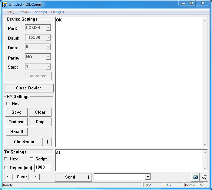
Then some useful configurations could be sent. Here are some samples of commands and responses.
Test serial connection, send “AT”, will return “OK”.
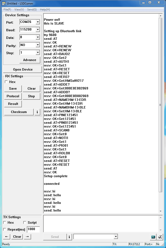
Restore factory settings, send “AT+RENEW”, return “OK+RENEW”.
Reset baud rate of serial port, send “AT+BAUD2”, return “OK+Set:2”.
Enable authentication, send “AT+AUTH1”, return “OK+Set:1”.
Reset the Bluetooth, send “AT+RESET”, return ”OK+RESET”.
Query firmware version, send “AT+VERS?”, return “OK+Get:HMSoftV217”.
Query MAC of EDR, send “AT+ADDE?”, return “OK+Get:000E0E002074”.
Query MAC of BLE, send “AT+ADDB?”, return “OK+Get:000E0B002074”.
Set the name of EDR, send “AT+NAMEHM-13-EDR”, return “OK+Set:HM-13-EDR”.
Set the name of BLE, send “AT+NAMEHM-13-BLE”, return “OK+Set:HM-13-BLE”.
Set the password of EDR, send “AT+PINE123451”, return “OK+Set:123451”.
Set the password of BLE, send “AT+PINB123451”, return “OK+Set:123451”.
Enable discovery and connectable, send “AT+SCAN0”, return “OK+Set:0”.
Enable notify information of connection, send “AT+NOTI1”, return “OK+Set:1”.
Notify information include address, send “AT+NOTP1”, return “OK+Set:1”.
Enable user key, send “AT+PIO01”, return “OK+Set:1”.
Set to Central mode, send “AT+ROLB1”, return “AT+ROLB1”.
Or Set to Peripheral mode, send “AT+ROLB0”, return “AT+ROLB0”.
We use two Bluetooth connected with PC, one was set as Central while the other is Peripheral. Several seconds later they find each other and the LED stop flash, connected!
Communicate with iPhone
This kind of Bluetooth module has two protocol: Bluetooth EDR(Enhanced Data Rate) and Bluetooth Low Energy. It can communicate with any device that has one of these protocols. Some Android phone with OS higher than 4.3 and iPhone4 or later have BLE ability. We use a iPhone to demonstrate how to use a cellphone to interact with Bluetooth.
Power the Bluetooth and configure it as Peripheral role. Search LightBlue in Apple Store and install it. Launch the app, you may find “HM-13-BLE” which we just renamed. Touch it to connect, then touch “Properties” to control it. The key “Hex” on the top right is for change data format, maybe String is easy to see. Hit “Listen for notifications” to enable data receiving. Then we can send data to PC through BLE, hit “Write new value” and write some words. Also PC can transfer data to iPhone with serial terminal.


Data transmission between Two Arduinos
Are you ready to code? It’s time to do something after practice. Prepare a pair of Bluetooth, and Arduino or other platform to control them. Here we use two Arduino Uno. Set up the connection as mentioned in section “Hardware Installation”.
The program of Central and Peripheral use the same code, the only difference is the micro define at the beginning of the program. To assign the Bluetooth to Central role, Just need to modify the text to “#define MASTER 1”, or “#define MASTER 1” if Peripheral role was assigned.
The initialisation program flow please refer to the following flow chart. First of all we need to distinguish the presetting baud rate of the Bluetooth. After this, send commands to restore factory settings, and change baud rate from 115200 to 9600 since software serial will not working well at high baud rate. Then other parameters were configured to the Bluetooth with Reset command in the final.
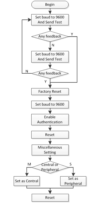
After the initialisation, the Central and Peripheral will do different things, the Central will send message to Peripheral interval and print what received from Peripheral while the Peripheral only responds the Central.
Click here to download the test code and open HM-13_SW.ino with Arduino IDE, compile and download to Arduino Uno. Remember to configure the Bluetooth to different role by modify the macro at the beginning. If you have any problem about how to start Arduino, please click here for some help.
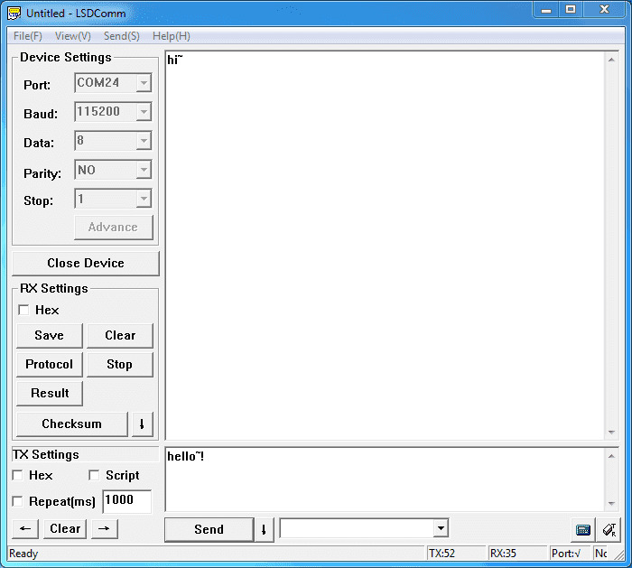
After downloading program, open two serial terminal windows, the LEDs on Bluetooth will flash, several seconds later, they stop to flash and keep on, this indicates that they connected to each other. According to the program is written, the Central sends message to the Peripheral continually and get feedback every time.

Resources
Last updated