Grove Base Booster Pack

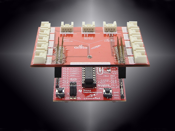
BoosterPacks are plug-in modules that can stack on top of the various LaunchPad kits to add additional functionality, such as sensors, displays, wireless modules & more. The Grove Base BoosterPack is a welcome addition to the LaunchPad/BoosterPack ecosystem, enabling any LaunchPad to interface with the growing offering of Grove modules from Seeed Studio. The Grove Base BoosterPack offers a convenient and easy way for rapid prototypers to use more than one hundred Grove modules with standardized connectors, including sensors, actuators, displays, lights, motors and more.

What is Grove?
Grove is a modular, ready-to-use tool set that takes a building block approach to assembling electronics. The Grove system consists of a base shield and a large selection of modules that feature standardized connectors. The base shield allows for easy connection of any microcontroller to interface with the various Grove modules. Each Grove module addresses a unique function & the overall collection of modules expand a wide range of functionality - from a simple push-button to a complex heart rate sensor. Each one comes with clear documentation and demo code to help you get started quickly.
What is LaunchPad?
The LaunchPad is a set of Evaluation Kits from Texas Instruments. To introduce new functionality to the LaunchPad evaluation kits, we present the BoosterPack which acts as a plug-in board that fit on top of the LaunchPad baseboards. It offers a convenient and easy way for you to use more than one hundred Grove modules with standardized connectors, including sensors, actuators, displays, lights, motors and so on.
Features
Seeedstudio presents the newly launched Grove Base BoosterPack allowing Texas Instruments Launchpad to be connected closed with our Groves Family,further enabling rapid prototype and combinations with a range of Sensors, actuators,displays,lights,motors and etc.
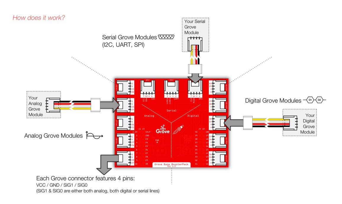
The Grove Base BoosterPack has thirteen Groves 4-pin standard interfaces ,including five analog, five digital and three serial port, acting as a plug-n-play expansion module on Launchpad based on MSP430 launchpad.It also provides various of tutorials on how to connect with TI MSP430, there are 11 different kinds of projects for reference prototype ,which offers a convenient way to guide your creativity.
There is a RED LED on the Grove BoosterPack. It will indicate the power supply.

Using the Grove Base BoosterPack
Using a 40-pin LaunchPad
i.e. MSP-EXP430F5529LP, EK-TM4C123GXL, etc
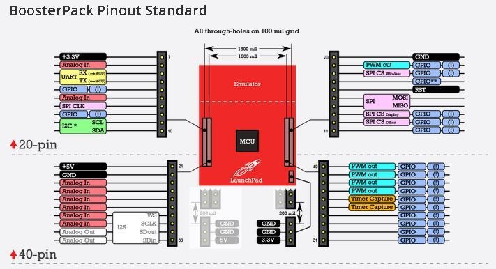
The BoosterPack was designed in a way to leverage pins in the “inner 20 pins” [21-40]. The pins are connected as shown below in the table:
Using the table below, developers should be able to read an analog value from a Grove module (i.e. potentiometer/turn knob) that is connected to Grove connector ‘J6’ by using the analogRead(24) API call with Energia.
Connector Type
Grove connector Label
GND
VCC
SIG1 (connection to the BoosterPack pin)
SIG0 (connection to the BoosterPack pin) *
Analog
J5
GND
3.3V
23 (analog capable pin)
22 (analog capable pin)
Analog
J6
GND
3.3V
25 (analog capable pin)
24 (analog capable pin)
Analog
J7
GND
3.3V
26 (analog capable pin)
25 (analog capable pin)
Analog
J8
GND
3.3V
27 (analog capable pin)
26 (analog capable pin)
Analog
J9
GND
3.3V
28 (analog capable pin)
27 (analog capable pin)
I2C
J10
GND
3.3V
10 (I2C SDA)
9 (I2C SCL)
UART
J11
GND
3.3V
4 (UART to MCU)
3 (UART from MCU)
SPI
J12
GND
3.3V
14 (SPI MISO)
7 (SPI CLK)
Digital
J13
GND
3.3V
39 (Digital/PWM pin)
40 (Digital/PWM pin)
Digital
J14
GND
3.3V
38 (Digital/PWM pin)
39 (Digital/PWM pin)
Digital
J15
GND
3.3V
37 (Digital/PWM pin)
38 (Digital/PWM pin)
Digital
J16
GND
3.3V
36 (Digital/PWM pin)
37 (Digital/PWM pin)
Digital
J17
GND
3.3V
35 (Digital/PWM pin)
36 (Digital/PWM pin)
Using a 20-pin LaunchPad
If you are using a 20-pin LaunchPad, you can use jumpers or jumper wire to make the appropriate connections between a Grove connector & the BoosterPack connector.
Using your specific LaunchPad’s pin out diagram, you can physically/electrically connect the Grove module to the appropriate pin. Pinout diagrams for each LaunchPad are available here: http://energia.nu/pin-maps/
With the help of these pin diagrams, you know which pin has the function you need. If you want to use Grove connector J5 for an analog Grove module (i.e. potentiometer knob), you can use the Energia pin maps to identify an analog-capable pin of the BoosterPack connector. Using a jumper of wire, you can connect pin number 22 with the analog-capable pin that is available. For example, if you are using an MSP-EXP430G2 LaunchPad, you can use a jumper or a cable to connect pin 22 with pin 2.
Supported Products
Grove List
Resources
Last updated