Grove 6 Axis Accelerometer And Compass V2.0
The Grove –6-Axis Accelerometer&Compass V2.0 is a 3-axis accelerometer combined with a 3-axis magnetic sensor. It is an upgraded version of Grove - 6-Axis Accelerometer&Compass V1.0 and based on the sensor module LSM303D which has a selectable linear acceleration full scale range of ±2g / ±4g / ±8g / ±16g and a selectable magnetic field full scale range of ±2 /±4 / ±8 / ±12 gauss. Both the magnetic parts and the accelerometer parts can be powered down separately to reduce the power consumption. The Arduino can get these data via the I2C interface with the given library for this module.
Specifications
Input Voltage: 5V
I2C Interface and selectable SPI Interface
Measuring scale selectable
6D orientation detection
2 independent programmable interrupt generators
Power-down mode
!!!Tip More details about Grove modules please refer to Grove System
Platforms Supported
Hardware Overview
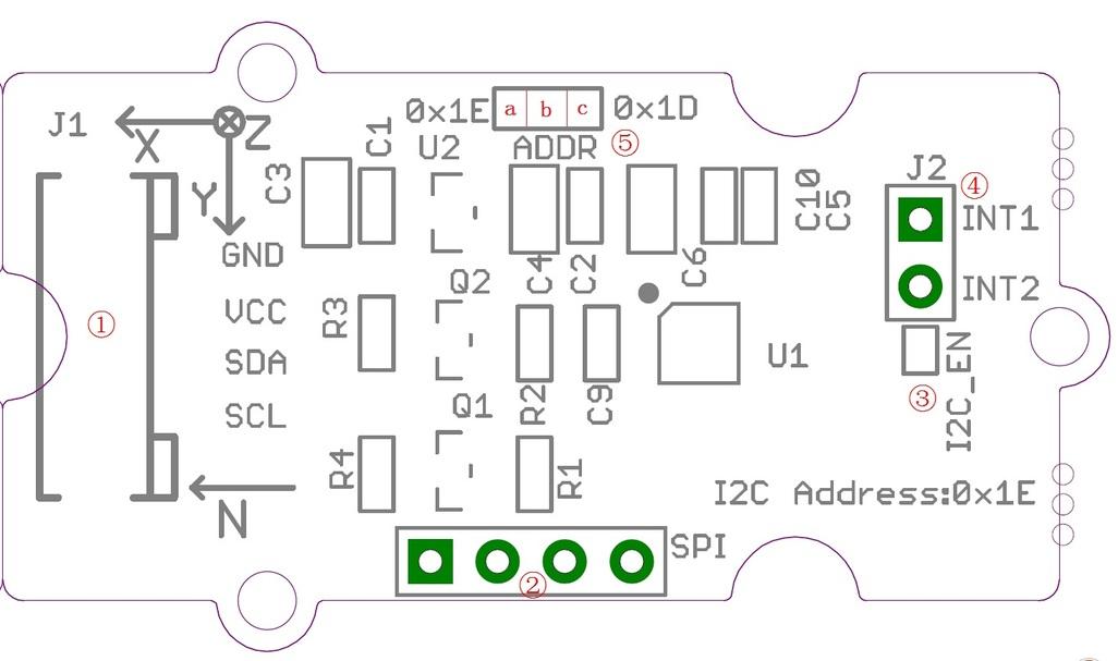
①Grove interface,connect to I2C
②SPI Interface
③I2C or SPI select pad(default is I2C), if want to use SPI, disconnect this pad
④Interrupt digital output
⑤Address select pad, default connected b and a address is 0x1E, if connect b and c address is 0x1D, if want to use SPI, disconnect this pad to either side.
Demonstration
The LSM303D is a 6D sensor module that contains a 3D accelerometer and a 3D magnetic sensor. It has an I2C digital interface so that the analog to digital converter is avoided.
The MCU can collect 6D sensor data directly through the I2C interface.OK, let's start on using this LSM303D 6D sensor module.
Hardware Installation
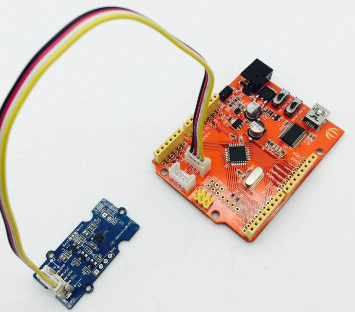
Hardware installation is very easy, because there's an I2C Grove in Seeeduino, so what we need to do is connect it to I2C Grove via a Grove cable.
Connect the Seeeduino to PC via a USB cable to power up this system.
Download Code and Upload
Download demo_code which shows how to calculate level and 6-Axis Accelerometer&Compass heading using the LSM303D.
Upload the Code.
Open the serial monitor, you will see the output result of Color Sensor as shown below:
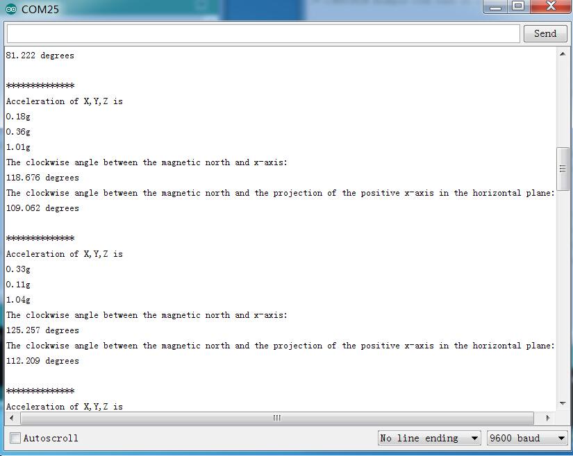
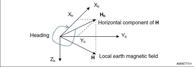
You can see the acceleration values and the clockwise angle between the magnetic north and x-axis.
The X/Y/Z shows the 3 axis acceleration; and then the angle between the magnetic north and x-axis calculated.
And also the the angle between the magnetic north and the projection of positive x-axis calculated.
Please refer here to know more about this parameter.
Notes
1. All ST MEMS accelerometers are factory calibrated, allowing the user to avoid any further calibration for most of the applications. However, to reach a heading accuracy of below 2°, an easy calibration procedure is needed.
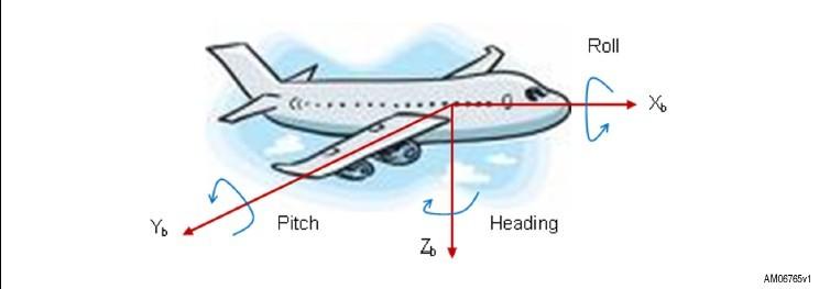
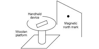
2. When test The clockwise angle between the magnetic north and x-axis, you can align the device Xa axis to any direction, but do not make it face down. Refer to the below picture:
Resources
Last updated
Was this helpful?