Grove Starter Kit v3
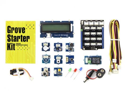
Grove is a modular electronics platform for convenient and rapid prototyping. Many configurations can be assembled without the need for soldering or breadboarding. Simply cable the Grove modules to the Grove shield and leverage the example code provided for each Grove module. The Grove Starter Kit contains a multitude of sensors and actuators, including support for audio, light, motion, tactile, and other interaction modes. So, you can start messing around at once with a wide variety of projects.
Preface
About Grove
Grove is a moderated, ready-to-use tool set. Much like Lego, it takes a building-block approach to assembling electronics. Compared with the traditional, complicated learning method of using a breadboard and various electronic components to assemble a project, Grove simplifies and condenses the learning process significantly. The Grove system consists of a base shield and various modules with standardized connectors.
The base shield allows for easy connection of any microprocessor input or output from the Grove modules. Every Grove module addresses a single function, such as a simple button or a more complex heart rate sensor. Each one comes with clear documentation and demo code to help you get started quickly.
Get to know Arduino
If this is your first time using an Arduino, you will need to complete the following steps:
The download address of the Grove - Starter Kit Sketchbook is here.
You are now ready to explore the Grove ecosystem.
Parts list
1*Base Shield
1*Grove - LCD RGB Backlight
1*Grove - Smart Relay
1*Grove - Buzzer
1*Grove - Sound Sensor
1*Grove - Touch Sensor
1*Grove - Rotary Angle Sensor
1*Grove - Temperature Sensor
1*Grove - LED
1*Grove - Light Sensor
1*Grove – Button
1*DIP LED Blue-Blue
1*DIP LED Green-Green
1*DIP LED Red-Red
1*Mini Servo
10*Grove Cables
1*9V to Barrel Jack Adapter
1*Grove starter kit Manual
1*Green Plastic Box
Modules Detail
Grove - Base Shield
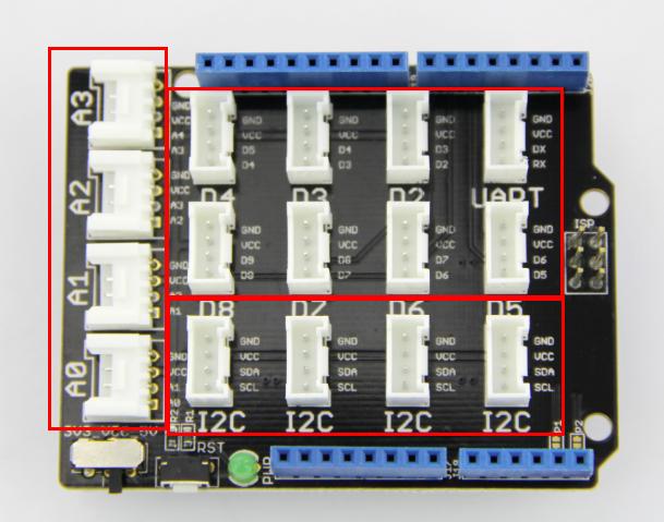
Let's start with the Grove base shield board. "Grove - Base Shield" is the new version of the "Electronic Brick Shield". The Base Shield is compatible with Seeeduino v3.0 (168p and 328p), as well as Arduino UNO and Duemilanove. There are 16 Grove ports on the base shield, divided into four functional areas: analog(4), digital(7), I2C(4), and UART(1).
Digital Ports
As the photo shows, there are seven digital ports, labeled D2-D8. Each of these handles a pair of digital pins (2/3 ... 8/9) on the Arduino Uno. They can be used for reading a digital sensor (e.g., pushbutton) or controlling a digital (or analog, via PWM) actuator. In any case, each port can only handle two logic states: 0 or 1.
Analog Ports
On the left-hand side are four Grove ports for taking analog readings. Analog sensors can return readings ranging from 0 to 1023. Compared with digital sensors that only return 0 or 1, analog readings are more detailed and precise.
I2C Ports
Below the digital ports are four I2C Grove ports. I2C is a low-speed bus protocol that transfers data via two wires: SCL and SDA. SCL is the clock line for synchronizing data transfer over the I2C bus; SDA is the data line.
For detailed information on how to use your Grove – Base Shield, go to Base Shield v2.
Grove - LCD RGB Backlight
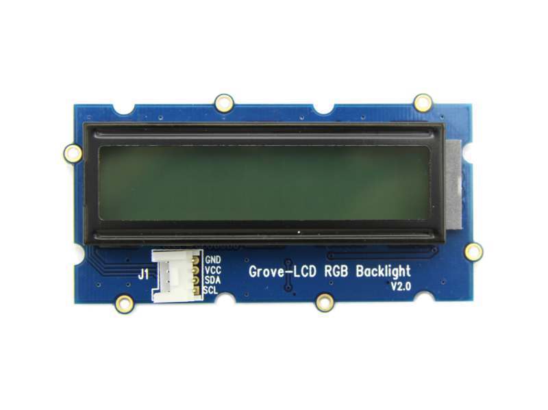
The Grove - LCD RGB Backlight supports text display, using user-defined characters. It enables you to set the backlight color, using the simple and concise Grove interface. It uses I2C as the communication method with your Arduino. So, the number of pins required for data exchange and backlight control shrinks from ~10 to 2, leaving more I/O capability for other challenging tasks.
Example
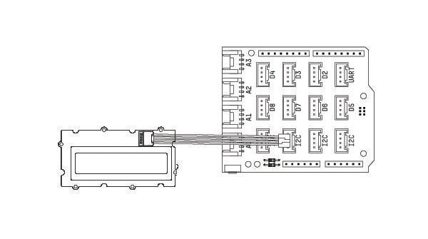
The example shows you how to print text on the screen and change the color of backlight. Find it via the path:
File -> Sketchbook -> Grove_RGB_Backlight_LCD -> HelloWorld
Tips
This is a 16x2 LCD screen. It is capable of displaying two rows of sixteen-character texts, supporting languages such as English and Japanese. You can also create and use custom characters by defining their display patterns. You can find an example of making a custom character here:
https://github.com/Seeed-Studio/Grove_LCD_RGB_Backlight/archive/master.zip
Grove – Relay
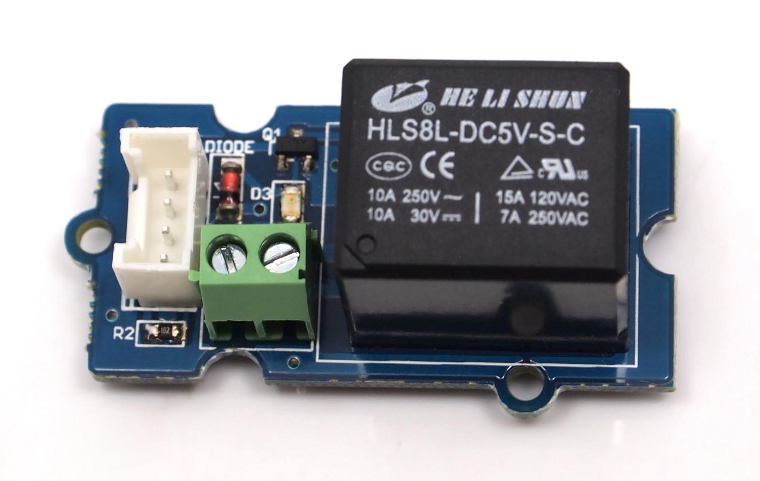
The Relay is a useful tool to magnify your Arduino’s control ability! Feed the control signal through the Grove interface and the relay open or close the external circuit that is connected to the screw terminals. The voltage of the external circuit can run up to 220V! So grab this relay and start some really tough projects!
Example
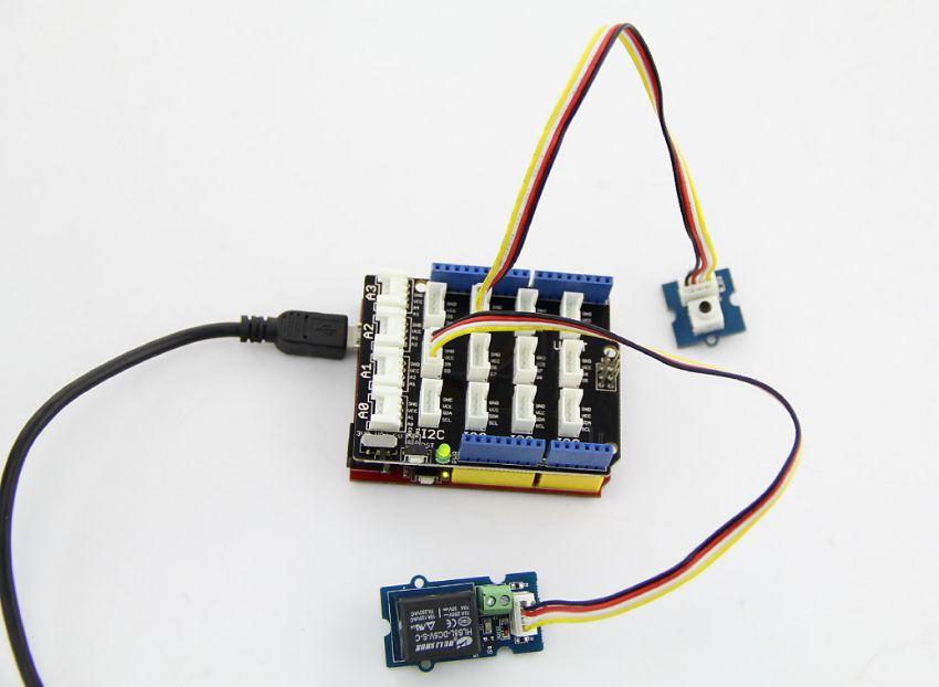
The example shows you how to control relay by a button: File -> Sketchbook -> Grove_Relay.
Tips
The Relay is an electronically-controlled mechanical switch. The size of a relay varies according to its capability for carrying current. The bigger a relay (essentially, just the plastic box part) is, the larger the current it can carry.
Please exercise great care when working with mains voltages – if in doubt, contact a professional such as a licensed electrician for help.
For detailed information on how to use your Grove – Relay, you can go to Grove – Relay page.
Grove – Buzzer
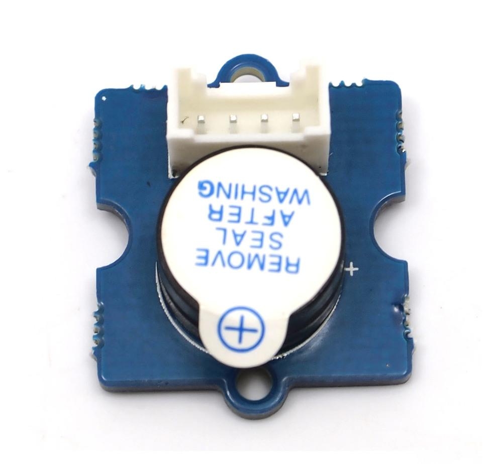
The Buzzer is a simple yet enjoyable Grove to use. It is piezoelectric speaker, coupled with a simple control circuit. If it is connected to a digital output, it will emit a tone when the output is high. Alternatively, it can be connected to an analog (really, pulse-width modulated digital) output to generate various tones and effects.
Example
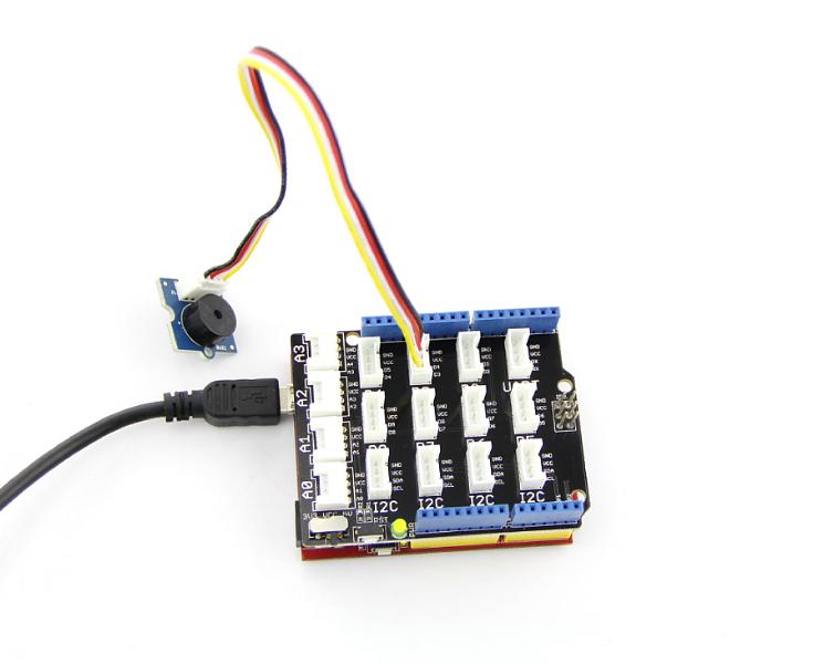
You can use the code for Grove – Button to make the buzzer beep when you press the button. However, Grove – Buzzer can be much more fun – it can play songs! This is a brief example from Oomlout.com, playing a household nursery rhyme – “Twinkle Twinkle Little Star”.
Find the example via the path below: File -> Sketchbook -> Grove_Buzzer
Tips
How does the Piezo buzzer actually work? Usually, there are two ceramic wafers in each Piezo buzzer. When different voltages are given to them, they attract or repel each other. The movement of these wafers causes air vibrations (i.e., sound). When the frequency of the vibration changes, the sound frequency will change accordingly.
For detailed information on how to use your Grove - Buzzer, go to Grove - Buzzer page
Grove - Sound Sensor
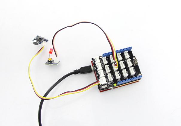
The Sound sensor module is a simple microphone. Based on an LM358 amplifier and an electret microphone, it can be used to detect the sound level in the environment.
Example
The code for the Grove – Sound Sensor can be used to control an LED light whose brightness reflects the intensity of ambient sound.
File -> Sketchbook -> Grove_Sound_Sensor
Tips
The electret microphone collects sound intensity for all frequencies, but a potentiometer can act as the doorman. For example, when you rotate the shaft completely clockwise, the potentiometer could let everything go through. When you rotate it completely counterclockwise, nothing would go through.
For a detailed information on how to use your Grove - Sound Sensor, go to Grove - Sound Sensor page
Grove - Touch Sensor
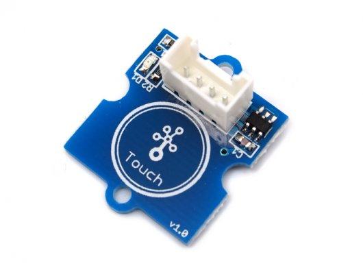
The Grove - Touch Sensor enables you to replace pressure on a button with contact on a detecting surface. It can detect the change in capacitance when a finger is nearby. So, whether your finger touches the pad directly or just stays close to it, the Grove - Touch Sensor would output HIGH.
Example
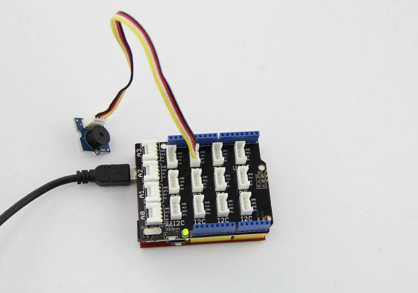
The code of Grove – Button works with this module. Find the example via the path below: File -> Sketchbook -> Grove_Buzzer
Tips
This is an alternative to the momentary contact button. The Grove – Touch Sensor detects the change in capacitance in the circular (unpainted) region on the bottom; the closer your finger is to this region, the larger the change in capacitance. Even if there is paper between your finger and the sensor, it will still function reliably.
For detailed information on how to use your Grove - Touch Sensor, go to Grove - Touch Sensor page.
Grove - Rotary Angle Sensor
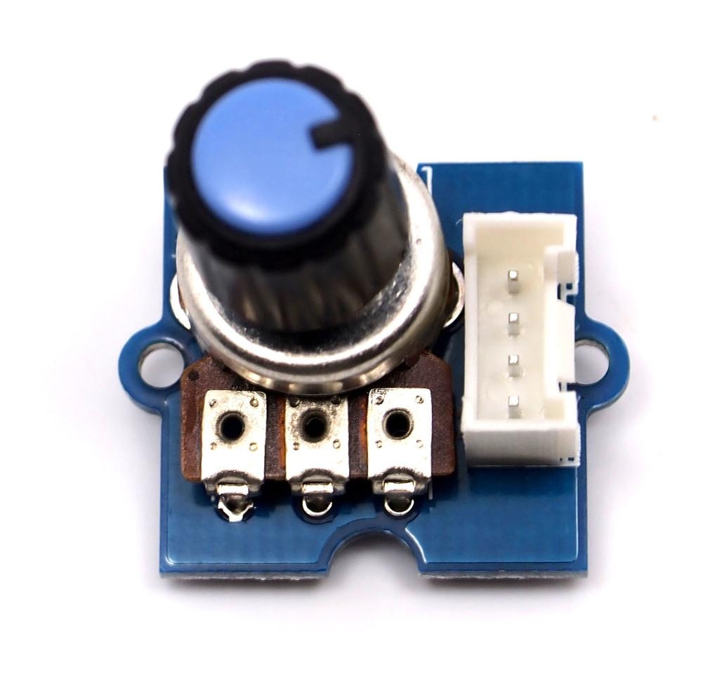
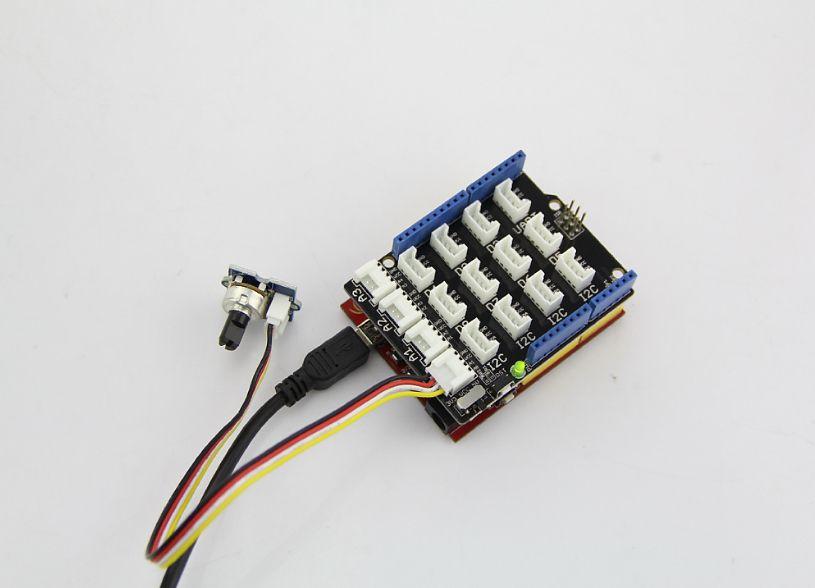
The Grove potentiometer produces analog output between 0 and VCC (3.3 or 5 VDC). The angular range is 300 degrees, with a linear change in value. The resistance value is 10k ohms, perfect for Arduino use. This may also be known as a “rotary angle sensor”.
Example
The example shows you how to read the value of a rotary angle sensor:
File -> Sketchbook -> Grove_Rotary_Angle_Sensor
Tips
A rotary potentiometer looks very similar to a rotary encoder, but they are not the same. A Rotary potentiometer is essentially a slide potentiometer, constructed in a circular shape. It reports, in an analog manner, the fraction of the resistive element being used by the sliding contact.
For a detailed information on how to use your Grove - Rotary Angle Sensor,you can go to Grove - Rotary Angle Sensor page
Grove – Temperature Sensor
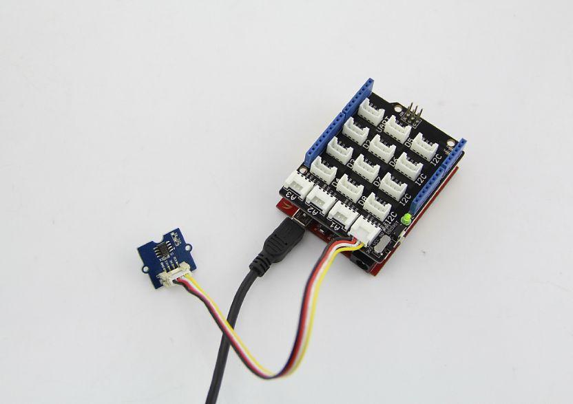
Grove - Temperature Sensor uses a thermistor which returns the ambient temperature. Our board then converts this voltage value measured by an analog input pin to a temperature. The operating range is -40 to 125 degrees Celsius.
Example
The example shows you how to convert the raw output of the sensor onto temperatures .You can see data in Celsius in the serial monitor.
File -> Sketchbook -> Grove_Temperature_Sensor.
Tips
Grove – Temperature Sensor is used to detect environment temperature.
For a detailed information on how to use your Grove - Temperature Sensor,you can go to Grove - Temperature Sensor
Grove - LED
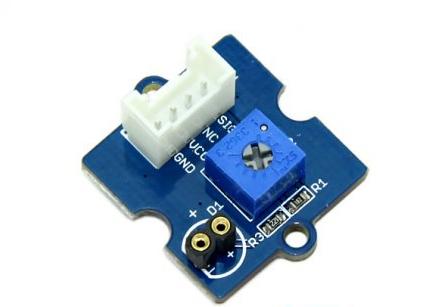
Grove - LED is designed for the beginners of Arduino/Seeeduino to monitor controls from digital ports. It can be mounted to the surface of your box or desk easily and used as pilot lamp for power or signal.
Example
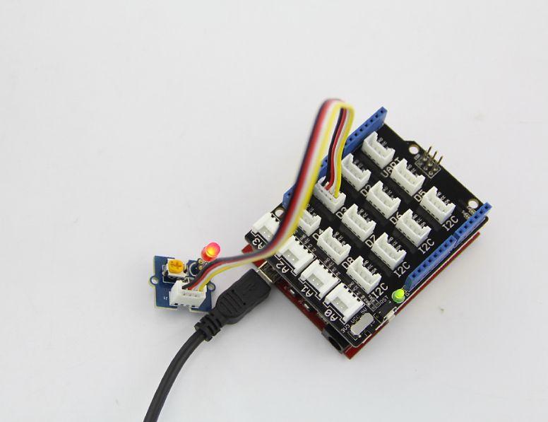
This example we make an LED light with breathing effects:
File -> Sketchbook -> Grove_LED
Tips
We prepare three colors of LED bulbs for you, you can get the color you want by changing the LED on the tiny Grove – LED Socket .LEDs have an cathode on the flat side of the bulb, and a anode on the round side of the bulb. The anode needs to be installed corresponding to the ‘+’ sign on the seat for the LED to work properly.
For a detailed information on how to use your Grove - LED,you can go to Grove - LED page
Grove - Light Sensor
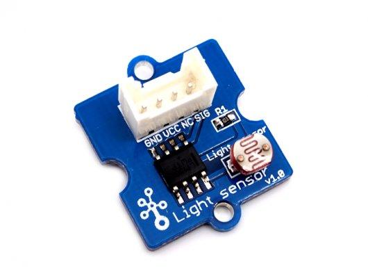
The light sensor, also known as the light dependent resistor (LDR). Typically, the resistance of the light sensor will decrease when the ambient light intensity increases.
Example
This example will turn on an LED when the light intensity falls below the preset threshold:
File -> Sketchbook -> Grove_Light_Sensor
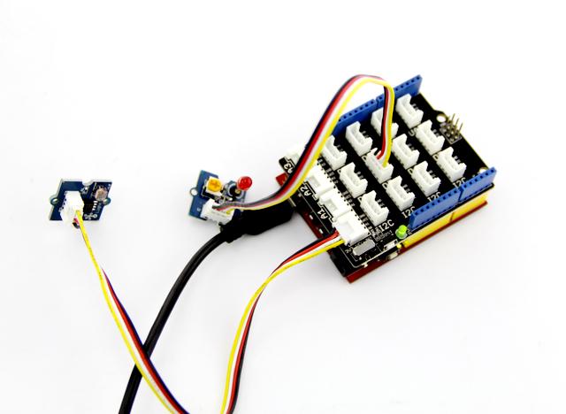
Tips
The output of the analog light sensor ranges from 0 to 1023, but the output is not linear with respect to the ambient light intensity.
For a detailed information on how to use your Grove - Light Sensor,you can go to Grove - Light Sensor
Grove – Button
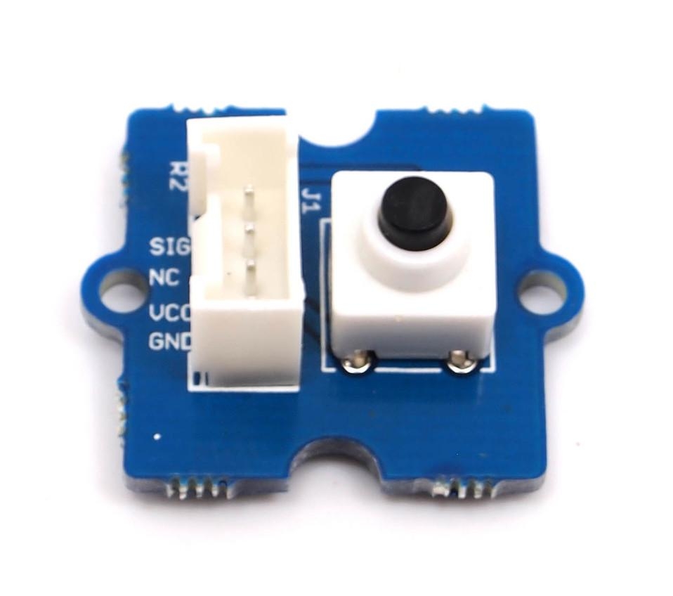
This new version of button Grove module contains one independent button, which are configured with pull-down resistor – ready for use with our microcontrollers as digital input. The button signals the SIG wire,NC is not used on this Grove module.
Example
This example shows you how to turn on or off an LED by this button.
File -> Sketchbook -> Grove_Button
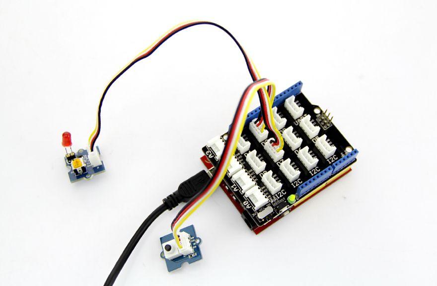
Tips
“Momentary” means the button rebounds after pressed .This button output HIGH when pressed, and LOW when released.
Grove - Servo
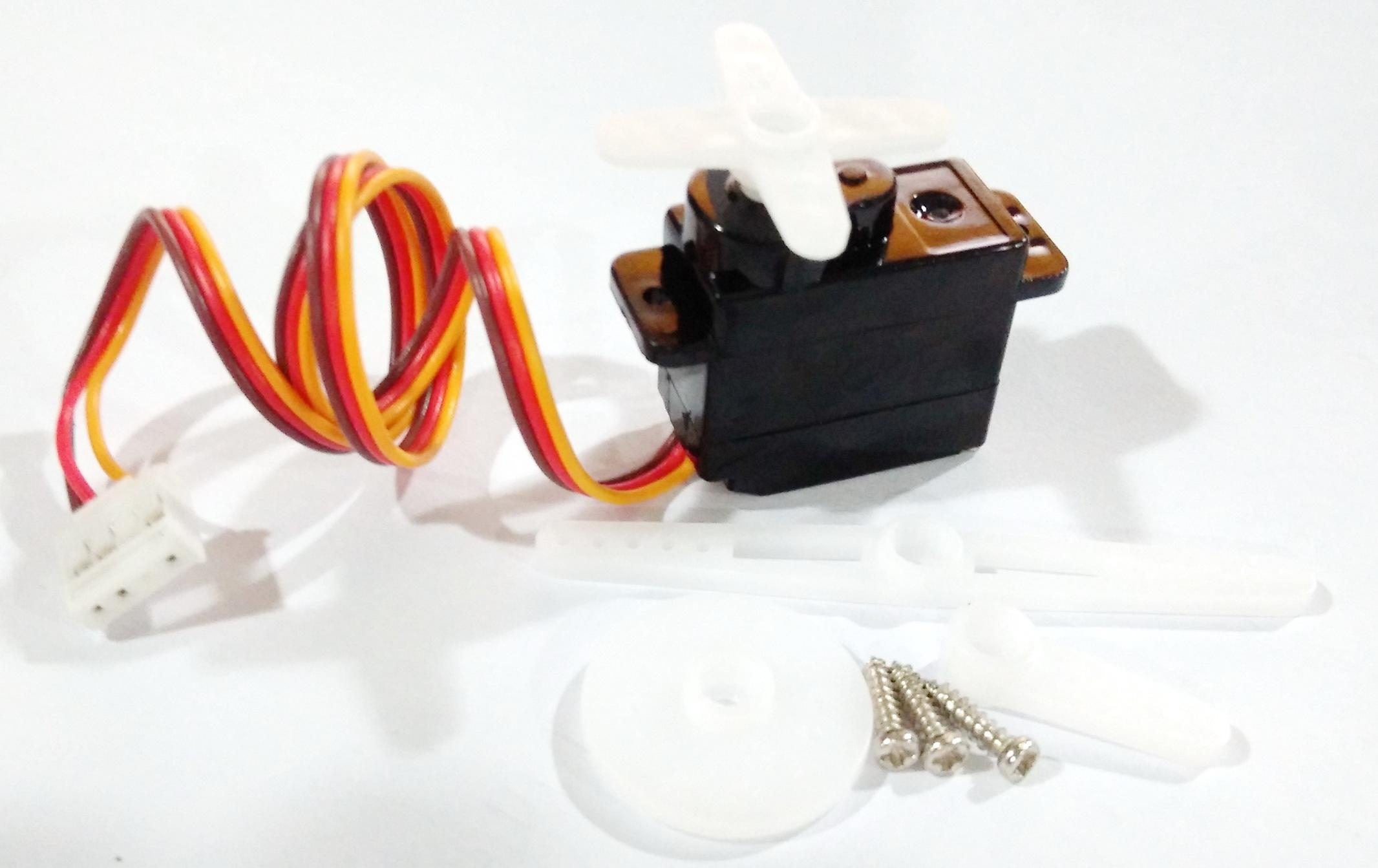
This is an actuator whose position can be precisely controlled.
Example
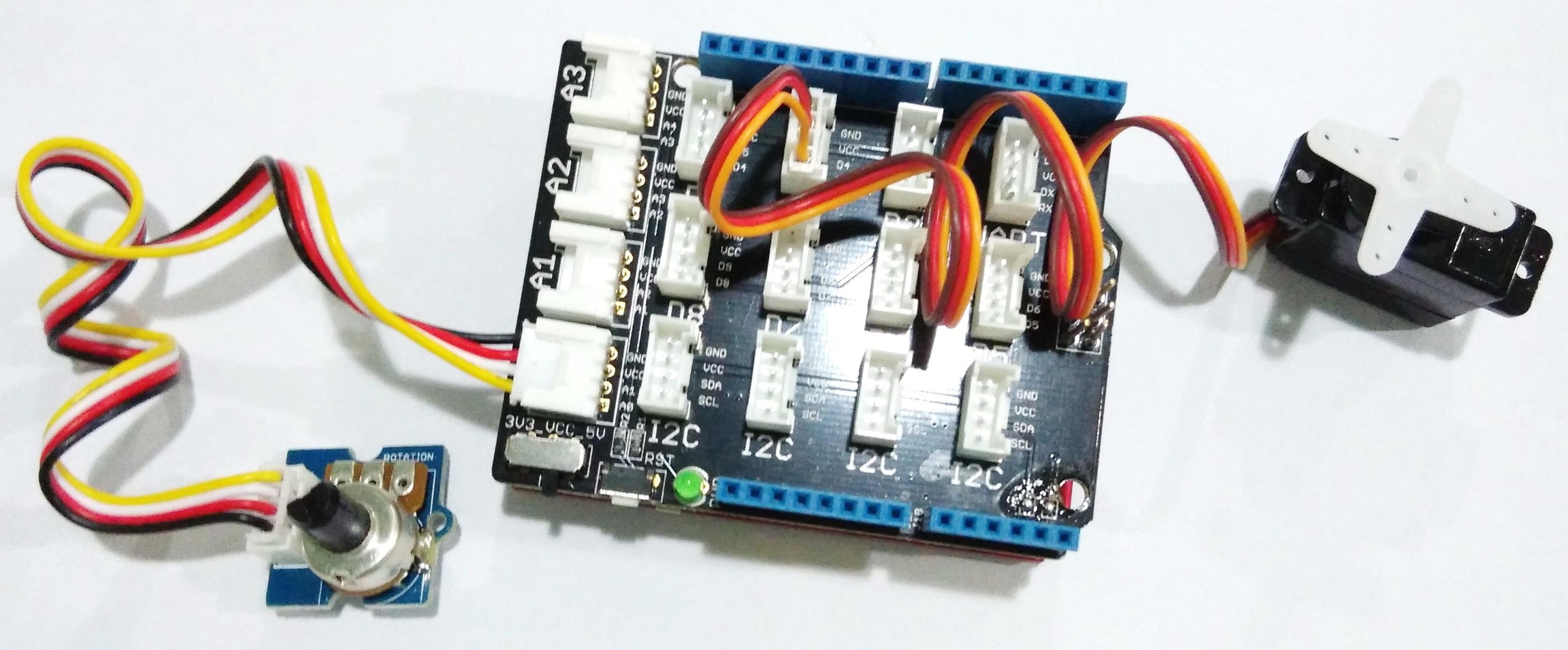
We prepared an example of how we use a potentiometer to control the position of the servo:
File --> Sktechbook --> Servo
Tips
Grove – Servo has mounting hardware options for different purposes: you can use them to drive a small fan, lift an object, or mimic a clock hand.
Demo projects
1. A Cup Of Flowers
Description
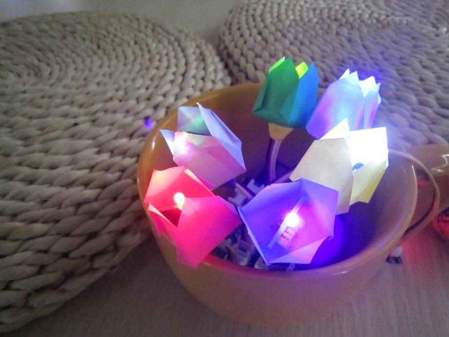
Would you like a cup of flowers to ease your exhausted heart? This project is made up of Grove – LED and one Grove – Touch Sensor. With the sensor being touched, those lovely LEDs will shine you a warm and comfortable light effect.
Materials List
1. Arduino x 1;2. Grove – Base Shield x 1;3. Grove – LED x 6;4. Grove – Touch Sensor x 1;5. 6 x 6cm Color paper x 6;6. 9V battery & 9V battery clip x 1.
!!!Note The number of LEDs is arbitrary. There are three of them contained in the basic kit. But you can increase or decrease it depending on the volume of your cup. I have a big cup here, so I added three more from our website.
Steps
1. Fold The Buds
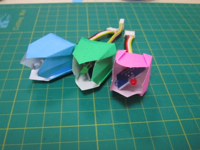
Choose one flower pattern you like and follow its steps to create some of them. One Google search may help a lot in finding one. There are so many origami hobbyists and artists over the Internet who’d like to share their handcrafts.
I chose tulip here, but sunflower, rose and lily also sound great!
When folding the bud, you need to leave a small hole on its button for the Grove cable to go through.
2. Set Up
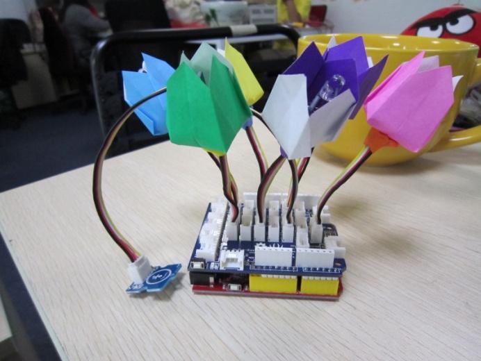
Connect the buds and the touch sensor onto the Grove – Base Shield with the 10cm Grove cable. And then upload the code to your controller.
3. Power Up & Settle Down
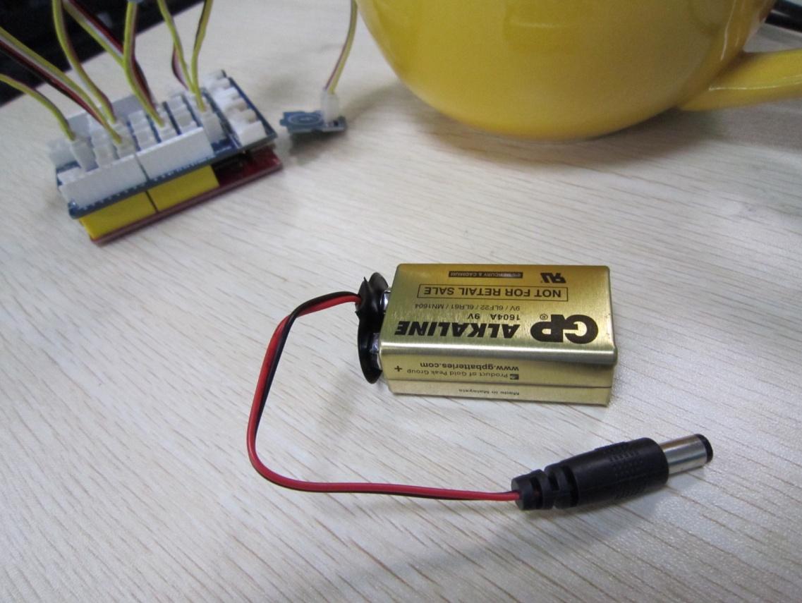
Use a portable 9V battery to provide power to the flowers and settle it down in the cup. Finished! Enjoy your cup of flowers!
2. How You Doing!
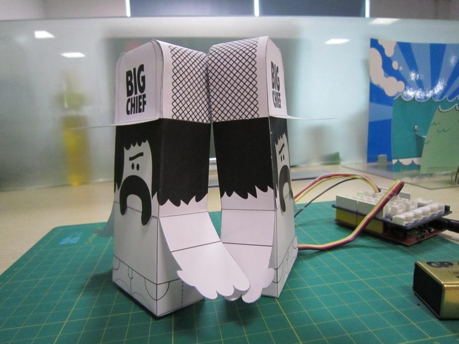
(downloaded form think.bigchief.it)
Description
How do you say hello to a friend? Big Chief would say “what’s better than a shake?” When one of these Big Chief paper toys lean his back against the others, they will shake to say hi! Materials List
1. Arduini x 1;2. Grove – Base Shield x 1;3. Grove – Magnetic Switch x 1;4. Grove – Vibrator x 1;5. Paper toys x 2;6. Magnet x 1;7. 9V battery & 9V battery clip x 1.
Note: The number of LEDs is arbitrary. There are three of them contained in the basic kit. But you can increase or decrease it depending on the volume of your cup. I have a big cup here, so I added three more from our website.
Steps
1. Print It Out!
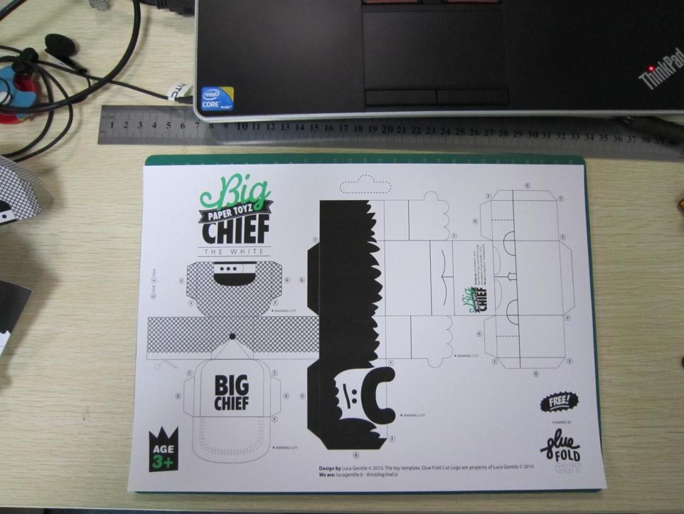
Choose one pattern you like over the Internet. Make sure there is enough room for a magnet or a magnetic switch plus a vibrator. Same as the origami flower above, you can find tons of them on the Internet.
2. Fill The Organs In
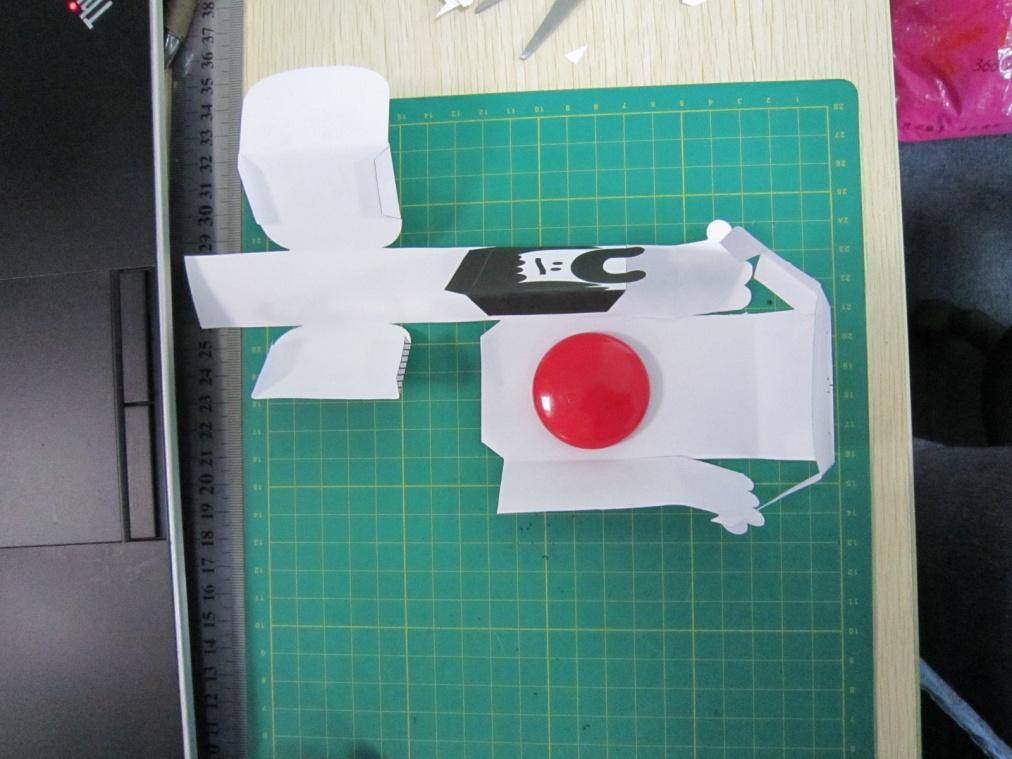
Focus when cutting the paper toys. Only in that way you can get a neat one. After that, time to fill some organs to them. I pasted a magnet on the back of Big Cihef A(let’s call it this name!). I stuck it there with double-sided adhesive tape.
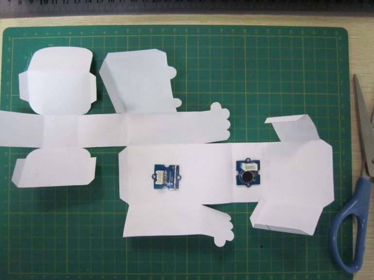
And for Big Chief B, I pasted a magnetic switch on his back, the same position as A, and a vibrator on his foots.
3. Glue Them Up
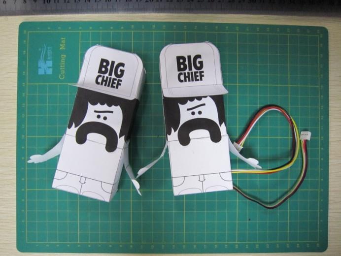
Carefully follow the instruction on the printed sheet. Plug the Grove cables into two Grove Modules we used in Big Chief B. Then you will get two cute paper toys like above.
4. Upload Program
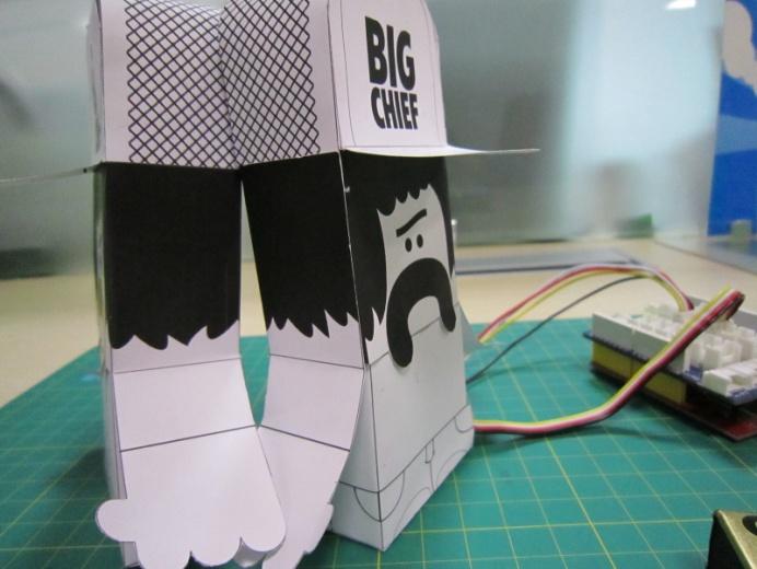
Upload the code below to your Arduino. By doing this, you bring life to them.
Features
Standardized – scalable Jigsaw shape, unified 4 pin connector, screw hole grid, edge solder pad, reduce duplicate developing, reuse in different projects to reduce environment impact
Compact – size from 2cm*2 cm, seamless combination, surface mounting components, 2.0mm pitch cable
Friendly – easy buckled connection, dumb proof, various extension modes, open for DIY, libraries and demo codes
Plentiful- large selection of common circuits from basic (button, LED) to professional sensor (Gyro, Compass), keep adding per demand, 3rd party contributions, reusable
Community based – satisfying needs through voting, democratized design, project and recipe sharing, profit sharing business pattern, Renting and Reuse
Resources
Acknowledgement
We would like to express our gratitude to Rich Morin who modified this document with more appropriate grammar and words.
Last updated