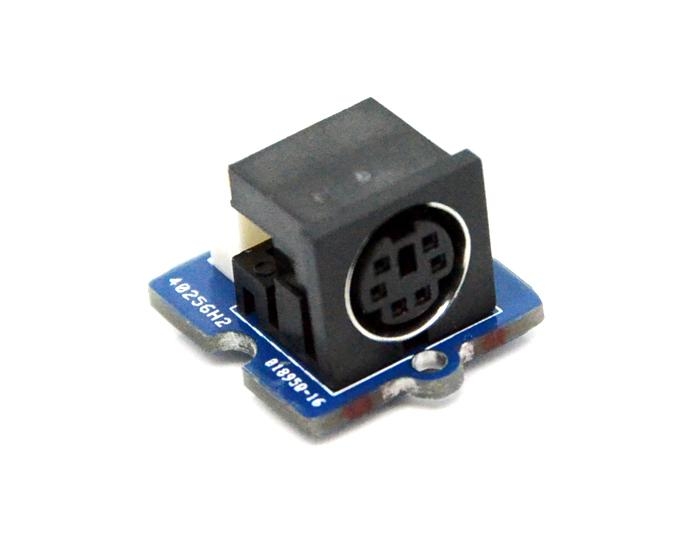
Grove PS 2 Adapter

The PS/2 Adapter enables you to connect a PS2 device to the Arduino/Seeeduino mainboards. With the help of PS2Keyboard/PS2MouseNlibrary, you can create the bridge between these PS2 device and Arduino/Seeeduino.
Features
Standard Grove interface
Standard PS/2 interface
Specification
Item
Min
Typical
Max
Unit
Voltage
4.75
5.0
5.25
V
Current
100
mA
Communication Mode
PS/2 Communication Protocol
/
Clock Frequency
10
15
33
KHZ
Application Ideas
PS/2 mouse and keyboard input
Usage
The PS/2 connector is a 6-pin Mini-DIN connector used for connecting keyboard and mouse to a PC compatible computer system.The PS/2 designs on keyboard and mouse interfaces are electrically similar and employ the same communication protocol. Today, this connector has been replaced by USB, but as Arduino/Seeeduino, it is also a good choice to use the PS/2 connector as it is more convenient and cheaper when you need a mouse or keyboard.
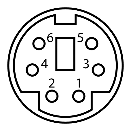
A PS/2 connector has 6 pins as you can see from the following diagram. Pin 1 and pin 6 are not connected. Pin 3 is for ground, and pin 4 is for power. The other 2 pins are for clock and data.

Pin
Name
Function
Correspond to the Grove Interface
1
+DATA
Data
DATA
2
NC
Reserved
-
3
GND
GND Line
GND
4
Vcc
+5DCV
VCC
5
+CLK
Clock frequency
CLK
6
NC
Reserved
-
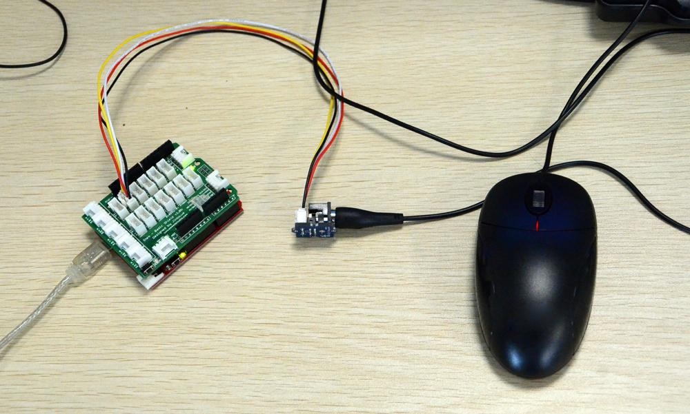
1.Plug the PS/2 mouse or keyboard to the Grove-PS/2 Adapter, and then connect Grove to the D5/D6 of Grove - Base Shield. You can change the digital port as you like. But, don't forget to change the port number in the definition of the demo code at the same time.
!!!Note Pin 5 is the mouse data pin, pin 6 is the clock pin.
2.Plug the Base Shield into Arduino/Seeeduino and connect Arduino/Seeeduino to PC via a USB cable.

3.Download PS2 Adapter library, Unzip and put them in the libraries file of Arduino IDE by the path: ..\arduino-1.0\libraries.
4.Restart the Arduino IDE, open one of the demo codes, for example ps2_mouse directly by the path:File -> Example ->PS2_Adapter->ps2_kbd.
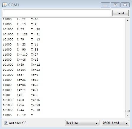
Please click here if you do not know how to upload. After uploading the firmware to the MCU,you can check the status via a Serial Monitor(9600 baudrate):

X ,Y output value changes correspondingly while the mouse move around.
Resources
Last updated