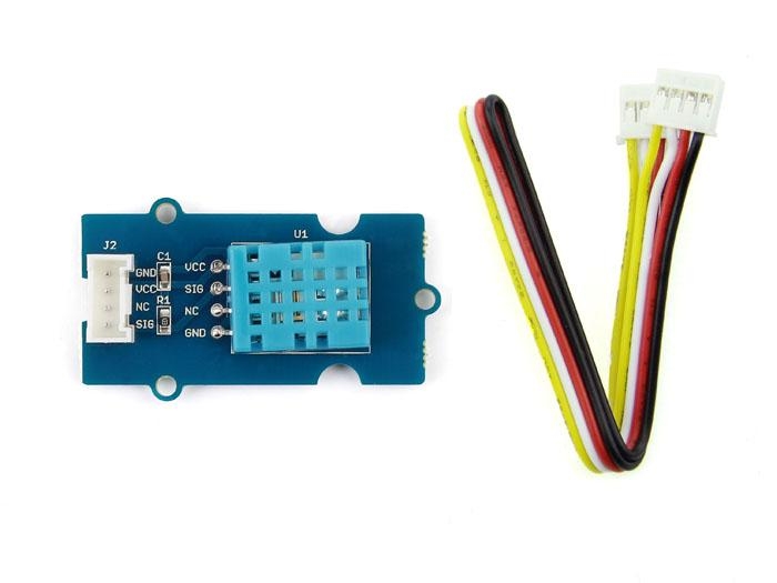
Grove Temperature And Humidity Sensor

This temperature & humidity sensor provides a pre-calibrated digital output. A unique capacitive sensor element measures relative humidity and the temperature is measured by a negative temperature coefficient (NTC) thermistor. It has excellent reliability and long term stability. Please note that this sensor will not work for temperatures below 0 degree.
Features
Relative Humidity and temperature measurement
Full range temperature compensation Calibrated
Digital signal
Long term stability
Long transmission distance(>20m)
Low power consumption
!!!Tip More details about Grove modules please refer to Grove System
Applications Ideas
Consumption product
Weather station
Humidity regulator
Air conditioner
Hardware Overview

Specifications
Key Specifications
Items
Min
PCB Size
2.0cm*4.0cm
Interface
2.0mm pitch pin header
IO Structure
SIG,VCC,GND,NC
ROHS
YES
Electronic Characterstics
Items
Conditions
Min
Norm
Max
Unit
VCC
-
3.3
-
5
Volts
Measuring Current Supply
-
1.3
-
2.1
mA
Average Current Supply
-
0.5
-
1.1
mA
Measuring Range
Humidity
20%
-
90%
RH
Temperature
0
-
50
°C
Accuracy
Humidity
-
-
±5%
RH
Temperature
±2
°C
Sensitivity
Humidity
-
1%
RH
Temperature
1
°C
Repeatability
Humidity
±1%
RH
Temperature
±1
°C
Long-term Stability
±1%
RH/year
Signal Collecting Period
2
S
Usage
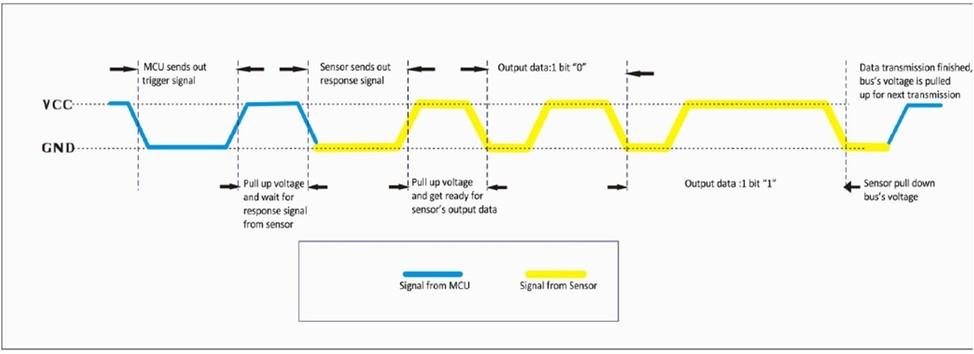
When MCU sends a trigger signal, sensor will change from low power consumption mode to active mode. After the trigger signal sensor will send a response signal back to MCU, then 40 bit collected data is sent out and a new signal collecting is trigged.(Note that the 40 bit collected data which is sent from sensor to MCU is already collected before the trigger signal comes.) One trigger signal receives one time 40 bit response data from sensor. Single-bus data is used for communication between MCU and sensor. The communication process is shown below:

It costs 5ms for single time communication.The high-order bit of data sends out first. Signal Data is 40 bit, comprised of 16 bit humidity data, 16 bit temperature data and 8 bit checksum.The data format is:
Programming
Connect the Temperature and Humidity sensor to analog port A0.Then you can use the following programme to gain the temperature and humidity of the environment.(The code is for seeeduino only,if you use seeeduino mega you should change the code a little. See below, if you use seeeduino mega, you should change PINC to PINF, change DDRC to DDRF and change PORTC to PORTF)

Resources
Last updated